- 您现在的位置:买卖IC网 > Sheet目录39247 > LM331MWC (NATIONAL SEMICONDUCTOR CORP) VOLTAGE-FREQUENCY CONVERTER, 0.1 MHz, UUC
Typical Applications (Continued)
DETAILS OF OPERATION, FREQUENCY-TO-
VOLTAGE CONVERTERS (
Figure 6 and Figure 7)
In these applications, a pulse input at f
IN is differentiated by
a C-R network and the negative-going edge at pin 6 causes
the input comparator to trigger the timer circuit. Just as with
a V-to-F converter, the average current flowing out of pin 1 is
I
AVERAGE = i x (1.1 RtCt)xf.
In the simple circuit of
Figure 6, this current is filtered in the
network R
L = 100 k and 1 F. The ripple will be less than 10
mV peak, but the response will be slow, with a 0.1 second
time constant, and settling of 0.7 second to 0.1% accuracy.
In the precision circuit, an operational amplifier provides a
buffered output and also acts as a 2-pole filter. The ripple will
be less than 5 mV peak for all frequencies above 1 kHz, and
the response time will be much quicker than in
Figure 6.
However, for input frequencies below 200 Hz, this circuit will
have worse ripple than
Figure 6. The engineering of the filter
time-constants to get adequate response and small enough
ripple simply requires a study of the compromises to be
made. Inherently, V-to-F converter response can be fast, but
F-to-V response can not.
DS005680-6
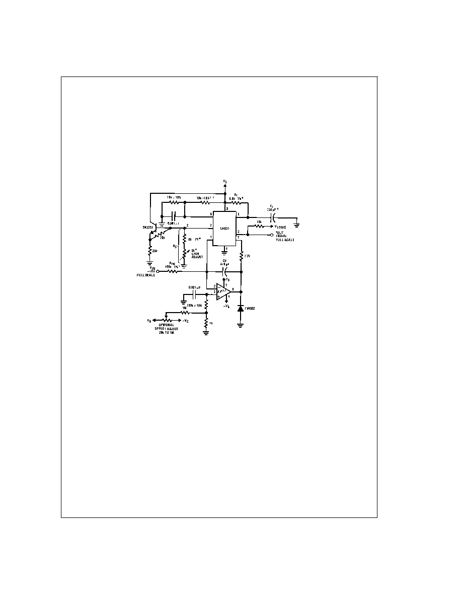
*Use stable components with low temperature coefficients.
See Typical Applications section.
**This resistor can be 5 k
or 10 k for VS=8V to 22V, but must be 10 k for VS=4.5V to 8V.
***Use low offset voltage and low offset current op amps for A1: recommended types LF411A or LF356.
FIGURE 5. Precision Voltage-to-Frequency Converter,
100 kHz Full-Scale, ±0.03% Non-Linearity
www.national.com
9
发布紧急采购,3分钟左右您将得到回复。
相关PDF资料
LM331MDC
VOLTAGE-FREQUENCY CONVERTER, 0.1 MHz, UUC
LM334Z-3
SPECIALTY ANALOG CIRCUIT, PBCY3
LM3355MM-4.1/NOPB
SWITCHED CAPACITOR REGULATOR, 1400 kHz SWITCHING FREQ-MAX, PDSO8
LM3355MMX-4.1/NOPB
SWITCHED CAPACITOR REGULATOR, 1400 kHz SWITCHING FREQ-MAX, PDSO8
LM3361AMX
FM, AUDIO SINGLE CHIP RECEIVER, PDSO16
LM3361AM
FM, AUDIO SINGLE CHIP RECEIVER, PDSO16
LM336Z-2.5B
1-OUTPUT TWO TERM VOLTAGE REFERENCE, 2.49 V, PBCY3
LM3460M5X-1.5/NOPB
1-OUTPUT THREE TERM VOLTAGE REFERENCE, 1.5 V, PDSO5
相关代理商/技术参数
LM331N
功能描述:电压频率转换及频率电压转换 RoHS:否 制造商:Texas Instruments 全标度频率:4000 KHz 线性误差:+/- 1 % FSR 电源电压-最大: 电源电压-最小: 最大工作温度:+ 85 C 最小工作温度:- 25 C 安装风格:Through Hole 封装 / 箱体:PDIP-14 封装:Tube
LM331N
制造商:Texas Instruments 功能描述:IC V/F CONVERTER DIP8 331
LM331N/A+
制造商:未知厂家 制造商全称:未知厂家 功能描述:Voltage-to-Frequency Converter
LM331N/B+
制造商:未知厂家 制造商全称:未知厂家 功能描述:Voltage-to-Frequency Converter
LM331N/HALF
制造商:Texas Instruments 功能描述:IC V/F CONVERTER DIP8 331
LM331N/NOPB
功能描述:电压频率转换及频率电压转换 PREC VLTG-TO-FREQ CONVERTER RoHS:否 制造商:Texas Instruments 全标度频率:4000 KHz 线性误差:+/- 1 % FSR 电源电压-最大: 电源电压-最小: 最大工作温度:+ 85 C 最小工作温度:- 25 C 安装风格:Through Hole 封装 / 箱体:PDIP-14 封装:Tube
LM331N/NOPB
制造商:Texas Instruments 功能描述:Voltage / Frequency (V/F & F/V) Converte
LM331NNOPB
制造商:Texas Instruments 功能描述: